Workshop Progress

Well… as the infrequent postings have given testament to, the family has been very preoccupied with preparations for the big move to NM. We are packing up belongings in cardboard boxes, finalizing plans and routes, and getting more and more excited about it.

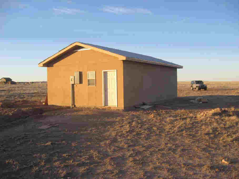
The workshop is nearly complete and we are very happy with the progress. We’ve had a nice driveway finished with stone and a small concrete slab poured at the workshop entrance. The interior is nearly complete. The job was made a bit more difficult for the subcontractors since hooking up the water and electricity are about the last things to happen. It no doubt made the cost higher since a generator had to be used for power, but it seems to have gone very well.

All that remains is the final plumbing hookup to the septic system, the installation of the pressure tank and pump for the well (as well as plumbing and wiring for that system) and the final installation of all electrical fixtures.

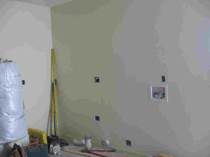
Here are a few photos of the progress as of this past weekend:

First, a view of the wall with water heater and laundry hookups. The pressure tank will be in the corner next to the water heater.
Next, a view of the interior of the garage looking toward the bathroom:
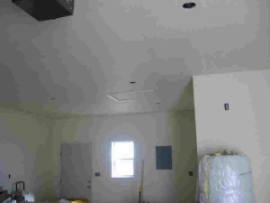
The photos were sent to us by my Dad, on a pdf. I’m sorry the quality of the resolution isn’t better, but it still gives a very good idea of the overall appearance.

We will have a somewhat circuitous route in our travels as we make the first trip from Georgia. We will be driving in a northerly route through Oklahoma so that we can pick up a second Clark Airborne bulldozer there. It takes us a bit out of the way, but is still much less time required than to make an entirely separate trip. We’ll be driving a caravan of sorts on this trip, driving both vehicles — the dually with the gooseneck trailer and two bulldozers plus parts and me in the Tahoe pulling a small U-Haul with the WLA motorcycle and bulky items packed to the gills.

{Can you notice the heavy emphasis on military vehicles that are featured in our belongings?}

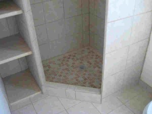
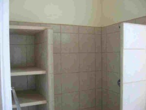
The guys did a very nice job on the bathroom, adding in a fully tiled shelving area. The glass shower door is still to be installed.
Once those tasks are complete, we’ll have the pad for the RV poured so that convenient living can happen while we build the house.

The move will require us to make another cross-country trek to haul all the belongings. We’ll return with just one vehicle and use a rented truck to load all the rest of our furniture from the house in Georgia back to New Mexico for the final trip.

{Did I mention that we’ll be making another detour on the trip back to Georgia in order to drop off some bulldozer parts in Texas along the way… just thought I’d mention that…}

31 days and a wakeup until the move begins!

More Clark Airborne Dozer Stuff

Making your own metal fuel lines: Part 2

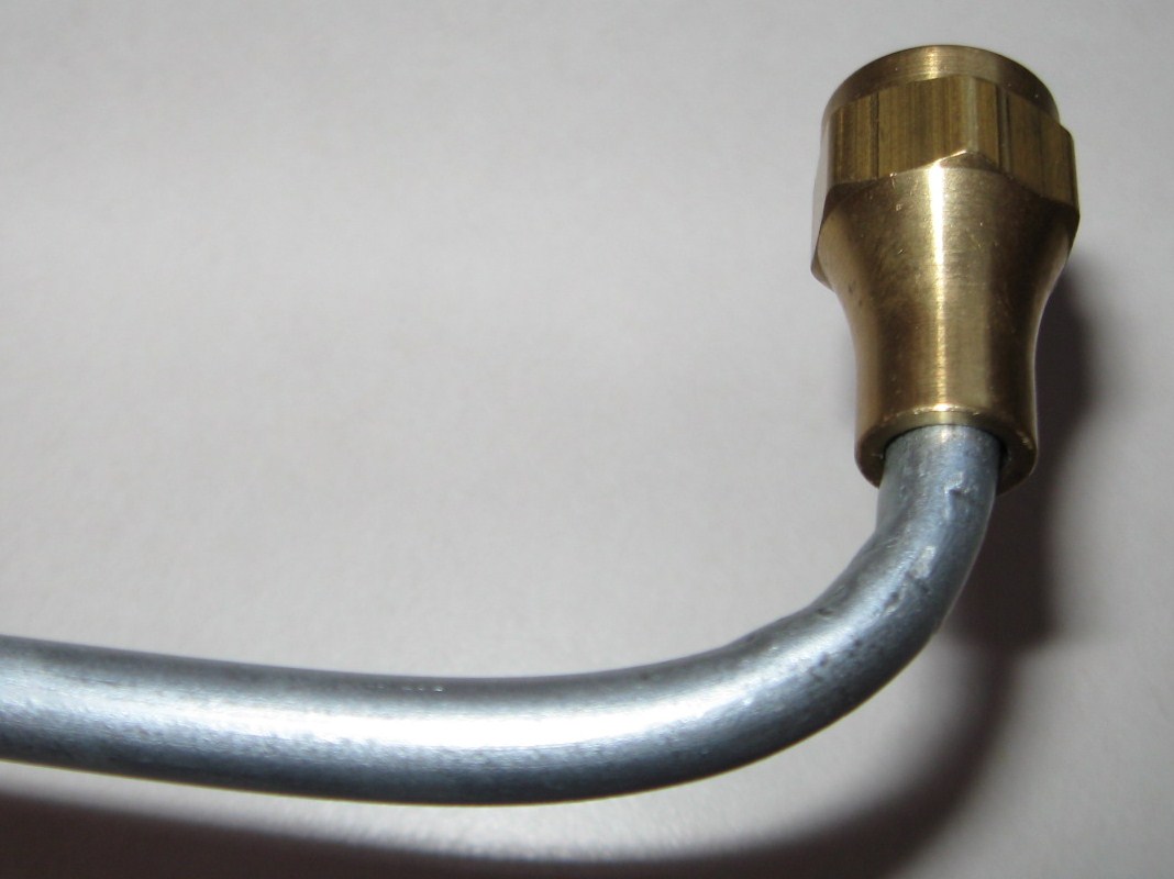
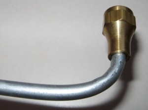
I wrote a previous blog article about making my own fuel lines for the Clark Airborne Tractor restoration project. This is the second part of the article which deals with making the flared endings for the tubes. I am using 37 degree flare tube fittings to seal my fuel lines. The components you are trying to mate together are; the beveled screw, the beveled cap and the flared tube. Each of the mated surfaces is beveled at a 37 degree angle (45 degree for higher pressure lines) so that when the cap is screwed against the flare of the tube and presses it up to the beveled screw end the mating of the 37 degree angled surfaces seals the line. If you create your flares properly and torque the cap and screw down properly, the fuel line will be sealed with no leaks, and no need for sealers or gaskets.
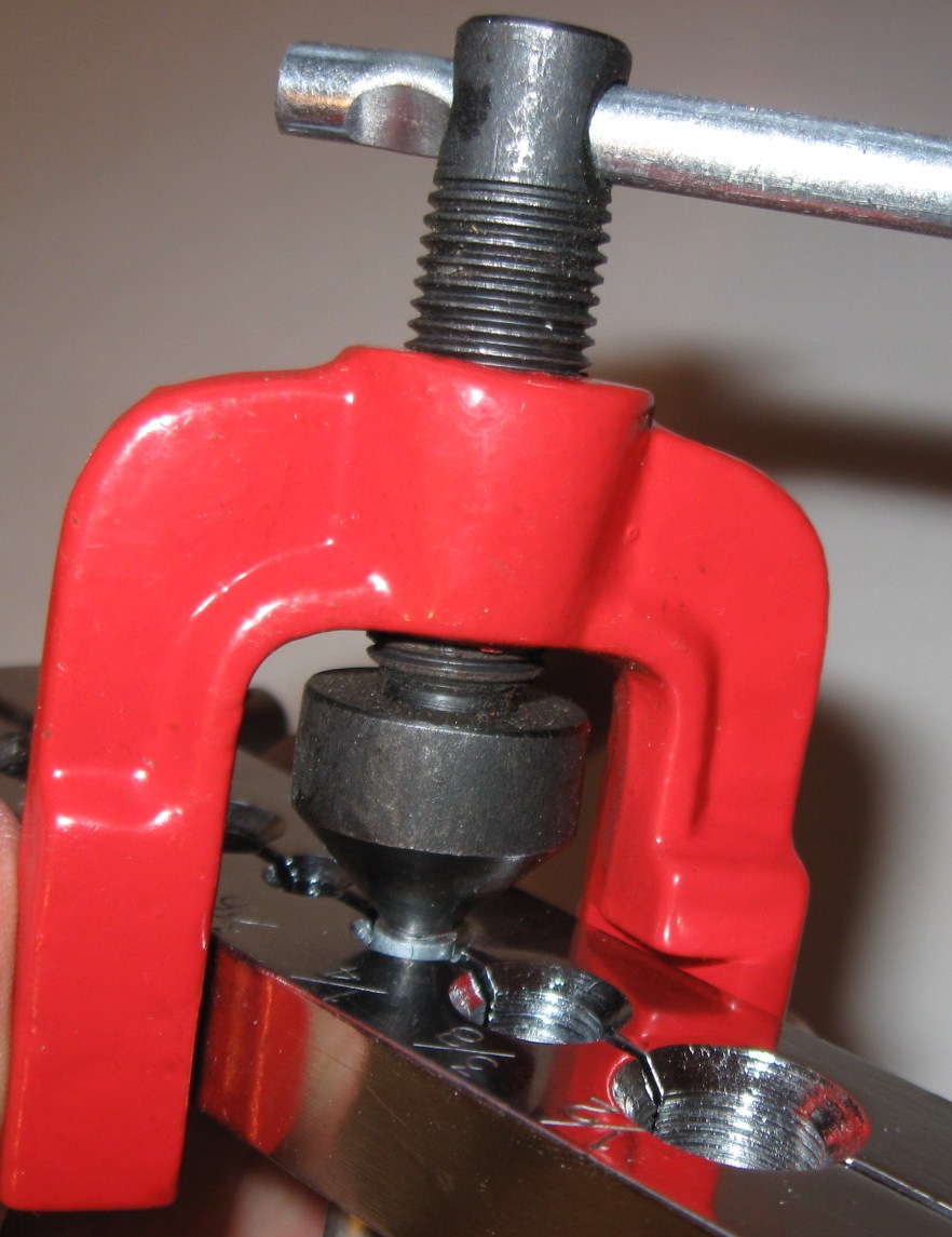
Making the flares is relatively easy as well, but takes some practice. Use some scrap tube and work several until you are comfortable. I am using the single flare. What you do is simply flare the pipe out to a 37 degree angle so that it can seal up between the screw and cap. The process involves the following steps:

1. Cut your pipe end to size.

Prepare the pipe end

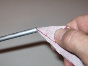
2. Use a small file and de-burr the inside of the tube to ensure it does not crack or split when being flared outward. You may also want to use some fine sandpaper to clean the edges up a bit. The smoother the metal is, the less chance there is for splitting.

3. Insert the cap fitting on the tube with the threaded ends toward the end of the tube. This is easy to forget sometime, and if you start the flaring process without the cap you’ll have to bend a new piece of tube, because once both flares are made, the cap will not slide on the end over the flare!

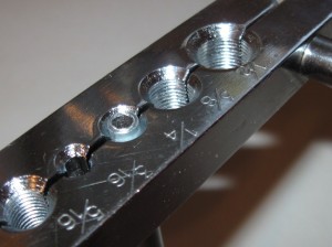
4. Insert the tube to be flared into the proper diameter hole of the vice exposing a very short length of the tube. If you expose too much of the tube, your flare will be too big for the cap. Clamp the vise closed

5. Put a light coating of oil on the end of the pointed flare tool to aid the process of expansion of the flare.

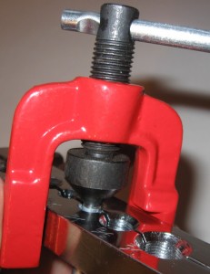
6. Insert the beveled end of the flaring tool using the vice and screw it gently down until the flare is shaped

7. Inspect and clean

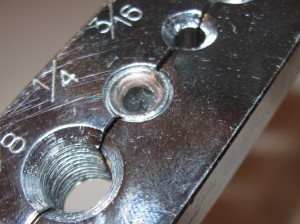
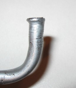
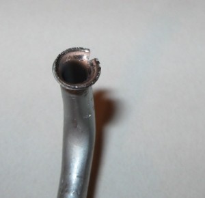
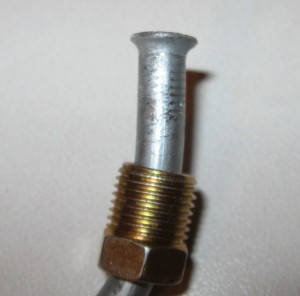
Here are some examples of my various previous attempts.

Oops!

The first one shows an off-kilter flare. It will not seat properly and the line will leak. This was caused by not clamping the tube fully down or by having the flare wedge off centered when screwing it down.

The second tube has split. This is usually because too much tube is exposed above the face of the clamping bar. It should be almost level with the top, or slightly above the top surface of the clamping bar.

Success.

The final example is fairly decent. It should hold pressure and provide a good seal.

If you liked this article, you’ll probably be interested in my previous post on the subject that you can find here: Making Your Own Metal Fuel Lines.

Home Mechanics – Making Your Own Metal Fuel Lines

More Clark Airborne Dozer Stuff:

Making Your Own Metal Fuel Lines Part 1


Metal Fuel Lines


During the rebuild of the Clark Airborne Dozer it was apparent that the rubber fuel lines were not original to the vehicle. The TM (Technical Manual) for the dozer specified metal fuel lines. I am trying as much as possible to restore the vehicle back to how it would have looked when the Airborne Engineers used it in 1944-45. The TM has a few sketchy/grainy diagrams of the routing of the fuel lines from the carburetor to the fuel sediment bowl (also missing). The lines are depicted in the BW photos as a light colored material, so I am assuming they are steel fuel/brake line material common to the era. The fittings are also a light color material and are either brass or some other metal. Restorers like to see original items built for the particular vehicle and were packaged years ago but never opened (called NOS, New Old Stock). Since the company manufactured all of their own parts and most of the fittings in 1943-44, there’s not much NOS laying around.

I’ve decided to use steel fuel line and brass fittings for the rebuild, and I’m going to have to make them myself, since the prospects of finding NOS fuel lines and fittings is extremely low. I suppose if I did find them they would be outrageously expensive. As a comparison, I needed a small metal lever type switch for the lights. It’s essentially an on/off switch specifically made for the Clark Bulldozer. It was $71 on the internet, but more importantly, it was probably the only one listed for sale in the last 6 months!! Keeping costs down is another reason to do it myself.

Tube Bending

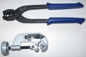
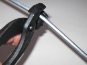
Following some basic research I settled on purchasing a hand-operated bending tool and a flaring tool. The bending tool is used to shape the metal line to the configuration needed. The TM shows a few bends and curves in the line, so I want to match those as close as possible. The hand-held tool that I have is essentially a set of pliers which grasps the fuel line for bending. The channel of the pliers has a groove which matches the diameter of the line. The channel is angled so as to create a supporting platform to “mold” the bend without kinking the line. It distributes the bending force equally along the side walls of the line so that it resists kinking. It is quite simple to make rather complex bends of varying angles and radius with the simple tool.

The particular model that I chose is easy to use, but it has one flaw. The “closure” that holds the tube firmly in place as you exert the pressure is made with a sharp edge and as it grips the tube it leaves a bit of a crimp/kink in the line which I do not like. It is essentially not a clean bend. There are other designs of hand held bending tools which may do a better job than the one I purchased. I assume that other types would not leave the tell-tale “crimp” marks as does the tool I purchased. The downside of that I think would be the bend is limited to a radius which matched the size of the bending wheel. Some of the models are relatively cheap, and there are more complex ones available that probably produce superior results. If I were going to bend a few thousand yards of line, I’d probably upgrade mine. For the simple jobs I have to do I am relatively happy with the results. I purchased my tools from Eastwood Company. The shipping was fast, price reasonable and the tool worked as advertised with the exception of the minor crimp marks which may be operator error: http://www.eastwood.com. I would recommend the following procedure for the type of pliers I used:
1. If you have an existing pattern, you can lay your straight tube alongside the bend pattern and make marks with a sharpie where you need to bend. With no pattern, you can eyeball the bends needed by taking a coat hanger and bending it “on-site” to match the bends you need with your tube. Use the actual components on the vehicle, bending the coat hanger by hand from the carburetor to the fuel sediment bowl in whatever configuration you need to fit the line. The coat hanger will bend easily and you will not need any tools. From this you have your pattern.
2. Place the tube in the pliers with the gripping orifice at the point where you want the bend to start, and the tube extending out along the angled channel.
3. Gently apply pressure on the piece of the tube that hangs out from the pliers along the pre-formed channels of the pliers. This will begin the bend at the prescribed angle.
4. You may need to move the pliers along the tube in the direction of the bend if you are making a more radical bend that is a tighter radius and more degrees of bend. This will prevent the line from kinking over.
5. With every minor bend, continue to compare your work to the pattern you made until the radius and angle of the bend match closely.
6. Once the tube has been bent to the prescribed configuration you can cut it to length with a standard pipe cutter, and then make the flares which will be discussed in part 2.

Cutting Tool

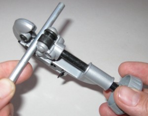
Using the cutting tool is quite simple. Place the tube in the cutting tool vice between the cutting wheel and the rollers. Screw down the rollers until the edge of the cutting wheel contacts the tube with slight pressure. Rotate the cutting tool around the tube for 1-3 revolutions. This makes the initial score in the tube. With every 2-3 rotations around the tube, tighten the clam down about ½ turn to score the tube deeper. Eventually the series of scores get deeper and deeper until the tube is fully cut. Resist the temptation to ‘cinch’ the clamp down tight as you will only crimp the tube and make a rougher cut. Be patient and make a clean cut.

In Part 2, I’ll cover the process of Tube Flaring.

.

Restoring a WWII Clark Airborne Tractor aka Dozer

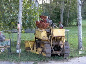
Used as a chicken roost by the former owner...

Why the heck would I want to do that? I have been doing research for a book I am writing on the 139th Airborne Engineer Battalion. They were the combat engineer element of the 17th Airborne Division who fought just west of Bastogne during the Battle of the Bulge, and they rode in gliders during Operation VARSITY as the 17th Airborne Division invaded Germany on 24 March 1945.

As I pored through the archival material at the National Archives I came upon an entry that said simply: “AIRBORNE CLARK TRACTOR damaged by mine. Operator injured.” It was 4 February 1945. For some strange reason I had to have one of these things. It’s not logical or practical, it just is. Since I am an avid collector of all things associated with the 139th it seemed logical to me!

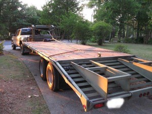
Gooseneck trailer with winch

A two month search uncovered a suitable project just south of Buffalo NY. I scheduled a pickup date, and I and one of my sons drove with a friend from work who wanted to visit his father in Buffalo. We arrived after a 928 mile trip. It took us exactly an hour to inspect, and winch the dozer onto the 20’ gooseneck trailer behind the Chevy Dually. I was impressed with the efficiency of our loading/safety team. The Dozer is not running, but free-wheeled nicely and the winch and pulley system tugged it right onto the trailer. I secured it with 4 heavy duty class 80 chains and 4 ratchet binders and off we went.

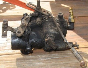
Since I am still three months (93 days, 4 hours and 27 minutes) away form the move to our homestead, I cannot disassemble the big parts. I still have to move it on and off of the trailer to get it to NM. I am able to work on small things such as distributor, generator, carburetor and a few other components. The time I have now has been used diligently to do research, find missing parts, connect with others who are doing the same (and there are dozens of other folks rebuilding Clark Airborne Dozers!!) and to learn more about the project. I filled the fluids, checked the basics and charged the battery. I have found that a recharged battery will turn the engine over, but there was not spark or fuel. I checked the compression and had between 90-99 psi across all 4 cylinders. The TM (Technical manual) calls for 85 psi minimum with no more than a 10psi difference between cylinders. I think I have a solid engine which needs some TLC.

Dirty Caburetor
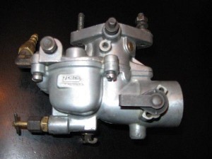
Clean Carburetor

So far I have rebuilt the distributor, found and had a generator rebuilt, worked on the carburetor, and am tending to minor details. It’s a fantastic project and when we get the home built, the boys and I will have a blast resorting this thing to fighting condition.

The value of what we are learning is immense. I see and appreciate the practicality of a non-electronic ignition system and an engine that you can reach all the components for and do not need ANY special tools to do all of the basic work, and much of the advanced repair. Hand tools, a manual, a source of spare parts and some confidence will allow me and the boys to tackle the

Used as a chicken roost by the former owner...

project. I know there will be some pitfalls and parts disappointments, but each of those will be challenges that will mold the young men into future problem solvers. You can follow the progress at the following sites:

A forum thread on the restoration progress here, and for information on parts, another thread devoted to that topic here.