More Clark Airborne Dozer Stuff:
Making Your Own Metal Fuel Lines Part 1
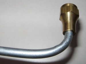
During the rebuild of the Clark Airborne Dozer it was apparent that the rubber fuel lines were not original to the vehicle. The TM (Technical Manual) for the dozer specified metal fuel lines. I am trying as much as possible to restore the vehicle back to how it would have looked when the Airborne Engineers used it in 1944-45. The TM has a few sketchy/grainy diagrams of the routing of the fuel lines from the carburetor to the fuel sediment bowl (also missing). The lines are depicted in the BW photos as a light colored material, so I am assuming they are steel fuel/brake line material common to the era. The fittings are also a light color material and are either brass or some other metal. Restorers like to see original items built for the particular vehicle and were packaged years ago but never opened (called NOS, New Old Stock). Since the company manufactured all of their own parts and most of the fittings in 1943-44, there’s not much NOS laying around.
I’ve decided to use steel fuel line and brass fittings for the rebuild, and I’m going to have to make them myself, since the prospects of finding NOS fuel lines and fittings is extremely low. I suppose if I did find them they would be outrageously expensive. As a comparison, I needed a small metal lever type switch for the lights. It’s essentially an on/off switch specifically made for the Clark Bulldozer. It was $71 on the internet, but more importantly, it was probably the only one listed for sale in the last 6 months!! Keeping costs down is another reason to do it myself.
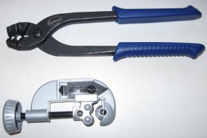
Following some basic research I settled on purchasing a hand-operated bending tool and a flaring tool. The bending tool is used to shape the metal line to the configuration needed. The TM shows a few bends and curves in the line, so I want to match those as close as possible. The hand-held tool that I have is essentially a set of pliers which grasps the fuel line for bending. The channel of the pliers has a groove which matches the diameter of the line. The channel is angled so as to create a supporting platform to “mold” the bend without kinking the line. It distributes the bending force equally along the side walls of the line so that it resists kinking. It is quite simple to make rather complex bends of varying angles and radius with the simple tool.
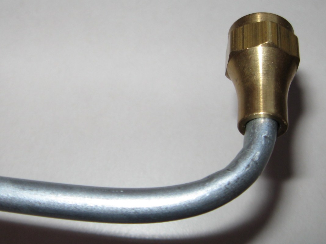
The particular model that I chose is easy to use, but it has one flaw. The “closure” that holds the tube firmly in place as you exert the pressure is made with a sharp edge and as it grips the tube it leaves a bit of a crimp/kink in the line which I do not like. It is essentially not a clean bend. There are other designs of hand held bending tools which may do a better job than the one I purchased. I assume that other types would not leave the tell-tale “crimp” marks as does the tool I purchased. The downside of that I think would be the bend is limited to a radius which matched the size of the bending wheel. Some of the models are relatively cheap, and there are more complex ones available that probably produce superior results. If I were going to bend a few thousand yards of line, I’d probably upgrade mine. For the simple jobs I have to do I am relatively happy with the results. I purchased my tools from Eastwood Company. The shipping was fast, price reasonable and the tool worked as advertised with the exception of the minor crimp marks which may be operator error: http://www.eastwood.com. I would recommend the following procedure for the type of pliers I used:
1. If you have an existing pattern, you can lay your straight tube alongside the bend pattern and make marks with a sharpie where you need to bend. With no pattern, you can eyeball the bends needed by taking a coat hanger and bending it “on-site” to match the bends you need with your tube. Use the actual components on the vehicle, bending the coat hanger by hand from the carburetor to the fuel sediment bowl in whatever configuration you need to fit the line. The coat hanger will bend easily and you will not need any tools. From this you have your pattern.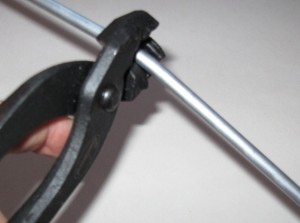
2. Place the tube in the pliers with the gripping orifice at the point where you want the bend to start, and the tube extending out along the angled channel.
3. Gently apply pressure on the piece of the tube that hangs out from the pliers along the pre-formed channels of the pliers. This will begin the bend at the prescribed angle.
4. You may need to move the pliers along the tube in the direction of the bend if you are making a more radical bend that is a tighter radius and more degrees of bend. This will prevent the line from kinking over.
5. With every minor bend, continue to compare your work to the pattern you made until the radius and angle of the bend match closely.
6. Once the tube has been bent to the prescribed configuration you can cut it to length with a standard pipe cutter, and then make the flares which will be discussed in part 2.
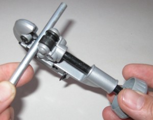
Using the cutting tool is quite simple. Place the tube in the cutting tool vice between the cutting wheel and the rollers. Screw down the rollers until the edge of the cutting wheel contacts the tube with slight pressure. Rotate the cutting tool around the tube for 1-3 revolutions. This makes the initial score in the tube. With every 2-3 rotations around the tube, tighten the clam down about ½ turn to score the tube deeper. Eventually the series of scores get deeper and deeper until the tube is fully cut. Resist the temptation to ‘cinch’ the clamp down tight as you will only crimp the tube and make a rougher cut. Be patient and make a clean cut.
In Part 2, I’ll cover the process of Tube Flaring.
.

