Finishing the Building Pad

Amidst a bout with kidney stones, extremely hot and windy weather, we finished our building pad and foundation lay out. I started by staking out a general layout of the foundation, placing corner stakes for the foundation in the location that we wanted the house to sit. This was not an exact layout just a general one done with a tape measure, stakes and string lines. Since we sit on 5 acres with no required set backs and no easements, I was not concerned with citing the corner of the house +/- ¼”. It was sorta a “looks about right” placement methodology. Had we been building in a subdivision, I would have used surveying equipment to place the foundation exactly in accordance with the plot plan.

With my foundation line in place, I used a Bobcat and removed the top few inches of top soil under the foundation and scraped away the vegetation around the foundation for several feet. The solid material under the pad has been undisturbed for millennium and we are about 16-24” above the first rock layer. My footers will extend, in most cases, through the soil and rest on the rock. Combined with rebar, 3000psi, fiberglass impregnated concrete; I think we will have a very solid foundation.

I then placed corner stakes for where I wanted the pad built up. I placed them 5’ on the outside of the foundation perimeter. That will give me a good buffer to work with when doing the trenching for the footers, and provide material to create a suitable run-off grade sloped away from the foundation. I then used the CST/Berger 800’ Dual Beam Rotary Laser to set a perfectly level string line at 6” above the highest grade.  The lowest point on the pad was 6” below the existing ground layer.

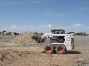
I ordered more than 200 tons of fill dirt and with a Bobcat I moved layers of dirt around the pad, using the string lines as both a perimeter guide and a height guide. As I moved the dirt I ensured I compacted as I drove the Cat in reverse with a majority of the weight of the machine on a nearly level bucket. The weight of the Cat and bucket being drug across the dirt aided in compaction. It is essential to compact between layers (4-8” recommended depending on soil quality) rather than filling completely and then compacting. Such a manner will result in only the top 6-12” being compacted and the bottom layer rather “fluffy” Over time the ground will settle resulting in foundation complications.

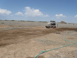
After the boys finished school, the assisted me in getting a fairly level pad (+/- 2”) by running supplemental string lines across the pad. Wherever the string touched the pad it was too high so I removed some dirt. Where the string was above the pad, I added fill and compacted. I was surprisingly able to build a fairly level pad using this method.  During the evening and into the next day, we sprinkled the pad heavily allowing the water to trickle down into the layers as best as possible to aid in further compaction.  I rented a walk behind vibrating roller and ran across the pad at least 4 times resulting in an even greater compaction.

I waited for the top of the pad to dry somewhat to prevent the caking of mud on the rollers. My concrete sub and a very seasoned home appraiser both were impressed with the work. Since I had never built a pad before I wanted a few folks to look at it.

The next step was to accurately (+/- 1/8”) lay out the exact perimeter of the foundation so that the footers could be trenched and the form boards could be placed. I purchased the CST/Berger 800’ Dual Beam Rotary Laser to do the work. I figured rental on the device for as many days as I would need it for the pad, the foundation, interior work, etc. would begin to add up.  It thought it would be well worth my time to buy it. It took me a while to learn the nuances of the device and make sure I was taking accurate readings and properly setting up the level. In the end I will have a lightly used, well cared for device that could be sold. I am certain this is a cost effective decision.

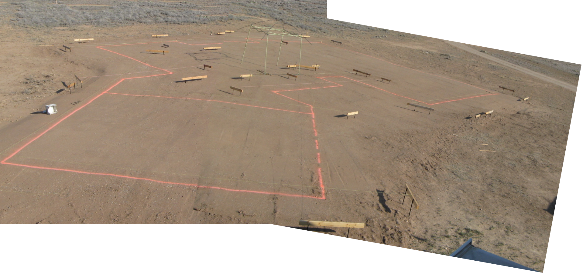
String lines, batter boards and orange marking paint define the outside edges of the foundation.

I established a  system of string lines and batter boards which defined the entire perimeter of the foundation. I used conventional methodology for this task, relying on 36” steel stakes rather than wooden stakes, given the density of the ground.  I took several diagonal measurements where possible to ensure everything was square. Given the dynamic nature of the perimeter, with lots of corners and 45 degree angles, taking the diagonal measurements was not easy. My worst measurement was 3/8” over a 60’ length.  I was striving for ¼”, but moving one stake impacts several others. It’s not as easy as squaring a rectangle with four corners. I think I will leave well alone and refine the “square-ity” in the framing stage.  Once I was pleased with the work, I used line marking spray to trace the outline of the foundation, which you can see from the image. The next phase will include trenching the footers and placing the form boards, followed by rough in plumbing.

Site Preparation — Building up the Pad

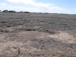
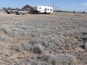
Before the buildup

This past week has been spent with various aspects of making life a bit more comfortable on the homestead. Such things as repairing a burnt out water heater caused us to learn a few new things(an error made by our electrician after power was supplied caused the tank to fill to only halfway, above which one of the heating elements burned out, shorted out the tank and began leaking).

We also began unpacking those things we will need during our stay in the RV and organizing things to allow some convenience. The bathroom inside the workshop is excellent… the washer and dryer are very handy… this is so much better already than the RV living we did during our evacuation from New Orleans after Katrina.

When we envisioned building ourselves, we really had not planned to do the site preparation ourselves, thinking it must be something to hire out. However, once we got the estimated cost of $7800 to build it up, we decided to put pencil to paper and see if that seemed reasonable.

After calling the local suppliers of fill dirt to compare pricing, getting information from them about compaction and delivery, we calculated how much fill dirt we would need to build up the pad to the desired 9″ or so. We also checked pricing on rental equipment and called up a brother in law with lots of dirt-moving experience. He provided some excellent tips regarding what type of equipment to rent, how to compact the dirt properly, etc.

After all this, we figured we could do it ourselves for less than half the cost. About $2400 in fill dirt ($11/ton in large loads; $16/ton for the last 15-ton load), and about $750 for a 3-day rental on the bobcat came to only $3150. We still need to rent the roller, but don’t expect that to be terribly expensive, perhaps no more than $150. On this first thing, we were able to save about $3500 by doing the work ourselves. Granted, it took a bit of time to master the technique of spreading the fill dirt evenly, so it may have taken an extra day of equipment rental, but it was still well worth the effort.

The work on preparing the site for building the house began on Monday morning with the renting of a bobcat for site preparation. Over the weekend, DH and the boys used the laser leveling gear to determine just how much slope there was to the building site. As it happens, it was only about 6″ total, so pretty level to begin with. After that, DH used the bobcat to scrape away the vegetation and dig the (very hard) surface off to prepare to add fill dirt.

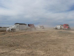
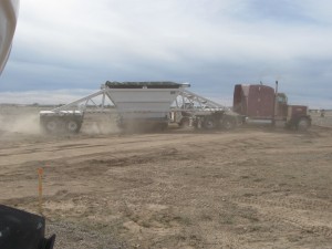
The delivery of the fill dirt was very interesting. Arriving in very large trucks, they delivered 25 tons per truck (100 tons total) the first day… another 100 tons the second day and a final 15 tons in a smaller truck to finish off on the third day. On the second day, during the dumping of the load from the second truck, we had a bit of a scare.

The truck backed up very quickly, coming within 6″ of the RV. My not very excitable husband got excited and yelled at the driver to stop… just in time. I was filming at the time, so it is documented… the noise of the trucks are such that you can’t really hear my husband saying (as he walked away): “Boy, that was close!”

DH took time to teach the boys how to drive the bobcat… both of them thought it was great fun. No doubt their computer game skills helped them a great deal! We have some vids to post showing their skills… The first is of the oldest boy (13 years old), working the magic:

The next video is of the youngest boy (11 years old), at the controls of the Bobcat:

The pad has now been built up to a fairly level state, with extra space built-up around the edges to allow for porches, patios, etc. This weekend has been spent watering the pad in preparation for rolling to compress the soil further next week.

Home Mechanics – Making Your Own Metal Fuel Lines

More Clark Airborne Dozer Stuff:

Making Your Own Metal Fuel Lines Part 1


Metal Fuel Lines


During the rebuild of the Clark Airborne Dozer it was apparent that the rubber fuel lines were not original to the vehicle. The TM (Technical Manual) for the dozer specified metal fuel lines. I am trying as much as possible to restore the vehicle back to how it would have looked when the Airborne Engineers used it in 1944-45. The TM has a few sketchy/grainy diagrams of the routing of the fuel lines from the carburetor to the fuel sediment bowl (also missing). The lines are depicted in the BW photos as a light colored material, so I am assuming they are steel fuel/brake line material common to the era. The fittings are also a light color material and are either brass or some other metal. Restorers like to see original items built for the particular vehicle and were packaged years ago but never opened (called NOS, New Old Stock). Since the company manufactured all of their own parts and most of the fittings in 1943-44, there’s not much NOS laying around.

I’ve decided to use steel fuel line and brass fittings for the rebuild, and I’m going to have to make them myself, since the prospects of finding NOS fuel lines and fittings is extremely low. I suppose if I did find them they would be outrageously expensive. As a comparison, I needed a small metal lever type switch for the lights. It’s essentially an on/off switch specifically made for the Clark Bulldozer. It was $71 on the internet, but more importantly, it was probably the only one listed for sale in the last 6 months!! Keeping costs down is another reason to do it myself.

Tube Bending

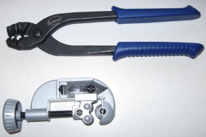
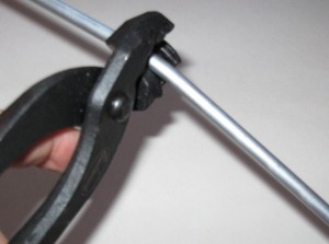
Following some basic research I settled on purchasing a hand-operated bending tool and a flaring tool. The bending tool is used to shape the metal line to the configuration needed. The TM shows a few bends and curves in the line, so I want to match those as close as possible. The hand-held tool that I have is essentially a set of pliers which grasps the fuel line for bending. The channel of the pliers has a groove which matches the diameter of the line. The channel is angled so as to create a supporting platform to “mold” the bend without kinking the line. It distributes the bending force equally along the side walls of the line so that it resists kinking. It is quite simple to make rather complex bends of varying angles and radius with the simple tool.

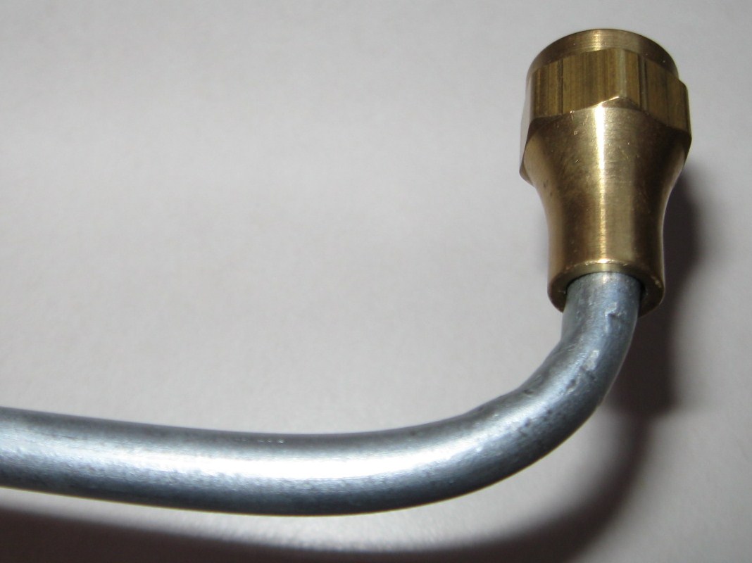
The particular model that I chose is easy to use, but it has one flaw. The “closure” that holds the tube firmly in place as you exert the pressure is made with a sharp edge and as it grips the tube it leaves a bit of a crimp/kink in the line which I do not like. It is essentially not a clean bend. There are other designs of hand held bending tools which may do a better job than the one I purchased. I assume that other types would not leave the tell-tale “crimp” marks as does the tool I purchased. The downside of that I think would be the bend is limited to a radius which matched the size of the bending wheel. Some of the models are relatively cheap, and there are more complex ones available that probably produce superior results. If I were going to bend a few thousand yards of line, I’d probably upgrade mine. For the simple jobs I have to do I am relatively happy with the results. I purchased my tools from Eastwood Company. The shipping was fast, price reasonable and the tool worked as advertised with the exception of the minor crimp marks which may be operator error: http://www.eastwood.com. I would recommend the following procedure for the type of pliers I used:
1. If you have an existing pattern, you can lay your straight tube alongside the bend pattern and make marks with a sharpie where you need to bend. With no pattern, you can eyeball the bends needed by taking a coat hanger and bending it “on-site” to match the bends you need with your tube. Use the actual components on the vehicle, bending the coat hanger by hand from the carburetor to the fuel sediment bowl in whatever configuration you need to fit the line. The coat hanger will bend easily and you will not need any tools. From this you have your pattern.
2. Place the tube in the pliers with the gripping orifice at the point where you want the bend to start, and the tube extending out along the angled channel.
3. Gently apply pressure on the piece of the tube that hangs out from the pliers along the pre-formed channels of the pliers. This will begin the bend at the prescribed angle.
4. You may need to move the pliers along the tube in the direction of the bend if you are making a more radical bend that is a tighter radius and more degrees of bend. This will prevent the line from kinking over.
5. With every minor bend, continue to compare your work to the pattern you made until the radius and angle of the bend match closely.
6. Once the tube has been bent to the prescribed configuration you can cut it to length with a standard pipe cutter, and then make the flares which will be discussed in part 2.

Cutting Tool

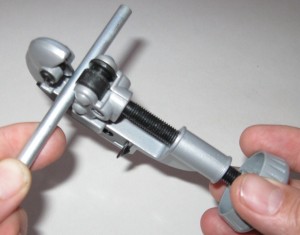
Using the cutting tool is quite simple. Place the tube in the cutting tool vice between the cutting wheel and the rollers. Screw down the rollers until the edge of the cutting wheel contacts the tube with slight pressure. Rotate the cutting tool around the tube for 1-3 revolutions. This makes the initial score in the tube. With every 2-3 rotations around the tube, tighten the clam down about ½ turn to score the tube deeper. Eventually the series of scores get deeper and deeper until the tube is fully cut. Resist the temptation to ‘cinch’ the clamp down tight as you will only crimp the tube and make a rougher cut. Be patient and make a clean cut.

In Part 2, I’ll cover the process of Tube Flaring.

.

Restoring a WWII Clark Airborne Tractor aka Dozer

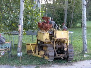
Used as a chicken roost by the former owner...

Why the heck would I want to do that? I have been doing research for a book I am writing on the 139th Airborne Engineer Battalion. They were the combat engineer element of the 17th Airborne Division who fought just west of Bastogne during the Battle of the Bulge, and they rode in gliders during Operation VARSITY as the 17th Airborne Division invaded Germany on 24 March 1945.

As I pored through the archival material at the National Archives I came upon an entry that said simply: “AIRBORNE CLARK TRACTOR damaged by mine. Operator injured.” It was 4 February 1945. For some strange reason I had to have one of these things. It’s not logical or practical, it just is. Since I am an avid collector of all things associated with the 139th it seemed logical to me!

Gooseneck trailer with winch

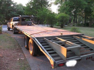
A two month search uncovered a suitable project just south of Buffalo NY. I scheduled a pickup date, and I and one of my sons drove with a friend from work who wanted to visit his father in Buffalo. We arrived after a 928 mile trip. It took us exactly an hour to inspect, and winch the dozer onto the 20’ gooseneck trailer behind the Chevy Dually. I was impressed with the efficiency of our loading/safety team. The Dozer is not running, but free-wheeled nicely and the winch and pulley system tugged it right onto the trailer. I secured it with 4 heavy duty class 80 chains and 4 ratchet binders and off we went.

Since I am still three months (93 days, 4 hours and 27 minutes) away form the move to our homestead, I cannot disassemble the big parts. I still have to move it on and off of the trailer to get it to NM. I am able to work on small things such as distributor, generator, carburetor and a few other components. The time I have now has been used diligently to do research, find missing parts, connect with others who are doing the same (and there are dozens of other folks rebuilding Clark Airborne Dozers!!) and to learn more about the project. I filled the fluids, checked the basics and charged the battery. I have found that a recharged battery will turn the engine over, but there was not spark or fuel. I checked the compression and had between 90-99 psi across all 4 cylinders. The TM (Technical manual) calls for 85 psi minimum with no more than a 10psi difference between cylinders. I think I have a solid engine which needs some TLC.

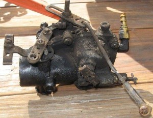
Dirty Caburetor
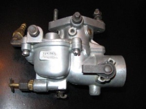
Clean Carburetor

So far I have rebuilt the distributor, found and had a generator rebuilt, worked on the carburetor, and am tending to minor details. It’s a fantastic project and when we get the home built, the boys and I will have a blast resorting this thing to fighting condition.

The value of what we are learning is immense. I see and appreciate the practicality of a non-electronic ignition system and an engine that you can reach all the components for and do not need ANY special tools to do all of the basic work, and much of the advanced repair. Hand tools, a manual, a source of spare parts and some confidence will allow me and the boys to tackle the

Used as a chicken roost by the former owner...

project. I know there will be some pitfalls and parts disappointments, but each of those will be challenges that will mold the young men into future problem solvers. You can follow the progress at the following sites:

A forum thread on the restoration progress here, and for information on parts, another thread devoted to that topic here.